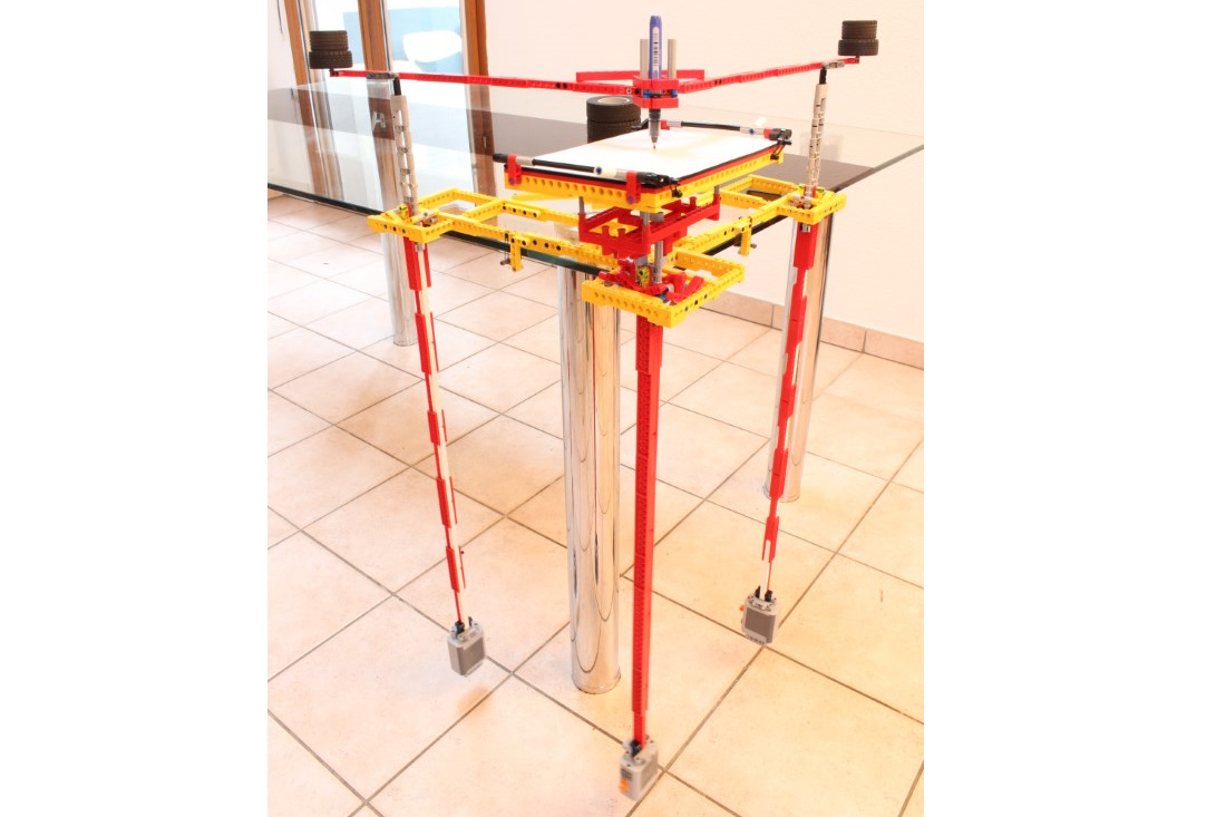
A lego interpretation of a 3 pendulums harmonograph drawing machine.
Drawing machine always fascinated me, especially when they are fully mechanical. For instance a Spirograph is a mechanical drawing harmonograph, it simply not uses the same basic functioning to draw. The purpose of the harmonograph here is to draw Lissajous curves thanks to 3 pendulum connected to arm and felt pen. The basic functioning is :
- The main pendulum is a free ball joint articulated on the frame and hold up the drawing sheet
- The two other pendulums are simple way articulated which are connected together to the red arm
- This arms is built in 90° angle shape in order that it can move in one direction thanks to the first pendulum, and in other (90° of the previous one) thanks to the second pendulum
- A felt pen is attached to the red arm and draw on the drawing sheet
To draw something, it needs only to launch one or two or three pendulum, therefore the system moves and draw something, especially geometric and continuous figures. Of course the result is always different depends of if you starts to move the main pendulum (give the main circular motion) and/or the two other (give the direction of circular motion and its evolution in time). And there are plenty of different harmonograph with more or less pendulum or connected pendulum or arms and so on. Here is the basic version of best known harmonograph.
Note that the main red arm is equipped with counter weight at these ends in order to have the less friction of the felt pen of the drawing machine. That is why I use also a felt pen because of its low needed force to draw. Thanks to that, The felt pen is maintained in upper position and when the arm is push down, the felt pen maintains its low position with low friction. Nevertheless, the friction is still here and the weight of pendulum not as heavy as the real harmonograph (made in steel), so well that the main pendulum slowly tends to apply circular motion to the other pendulum which reduce the autonomy and drawing time (around 1 or 2 minutes).
You can also see that I keep the idea of knife edge suspension for the pendulum from my Galileo clock. It enables to have very low friction and better Q factor on the pendulum (pendulum oscillate a long time). The main pendulum is built with two of this system in order to create a real ball joint articulation. You can note that the weight of main pendulum tend to taken apart one of the knife edge solution, need to improve it with technic brick instead of liftarm (which is of course better for rigidity but bad for compactness).
To conclude, I am pretty happy to have made this piece of mechanical engineering, there are several important point to succeed to get that, regarding the weight of pendulum, rigidity of frame, main arm and pendulum (all parasite vibration will reduce the efficiency) and of course lot of test to understand which movements in the pendulum make final drawing. It is still always different and sometime unexpected ! See the gallery to watch it.


(2) Comments
Hello, unfortunately, this model does not have a building instructions so can not be sold as a kit.
How can I buy the harmonograph?
Is it to sell with an instructional manual?
Is it possible to send it to México?
How much does it cost?
Comments are closed.